Designed and engineered all aspects of project
Ensured feasibility and that the project fit exactly where needed
Supervised all construction and logistics to ensure project was completed on within the 9 day time window
Was ultimately responsible for entire project
While deployed with Titan Salvage working on the Costa Concordia in Italy, a system to deploy a very large chisel (more like a pile driver) was needed extremely quickly. The chisel itself (60 feet long and weighing approximately 13 tons) was being trucked from UK while I was tasked with designing a mounting system for it that could be built and operational within 9 days. The chisel was to be used to level parts of the sea floor for large anchor blocks to be able to lie flat. Before the chisel left the UK warehouse it was measured and I had the measurements e-mailed to me. I then measured the work barge with nothing more complicated than a tape measure and hammer. I then spoke with the foreman to make sure I was clear on his requirements for chisel operations.
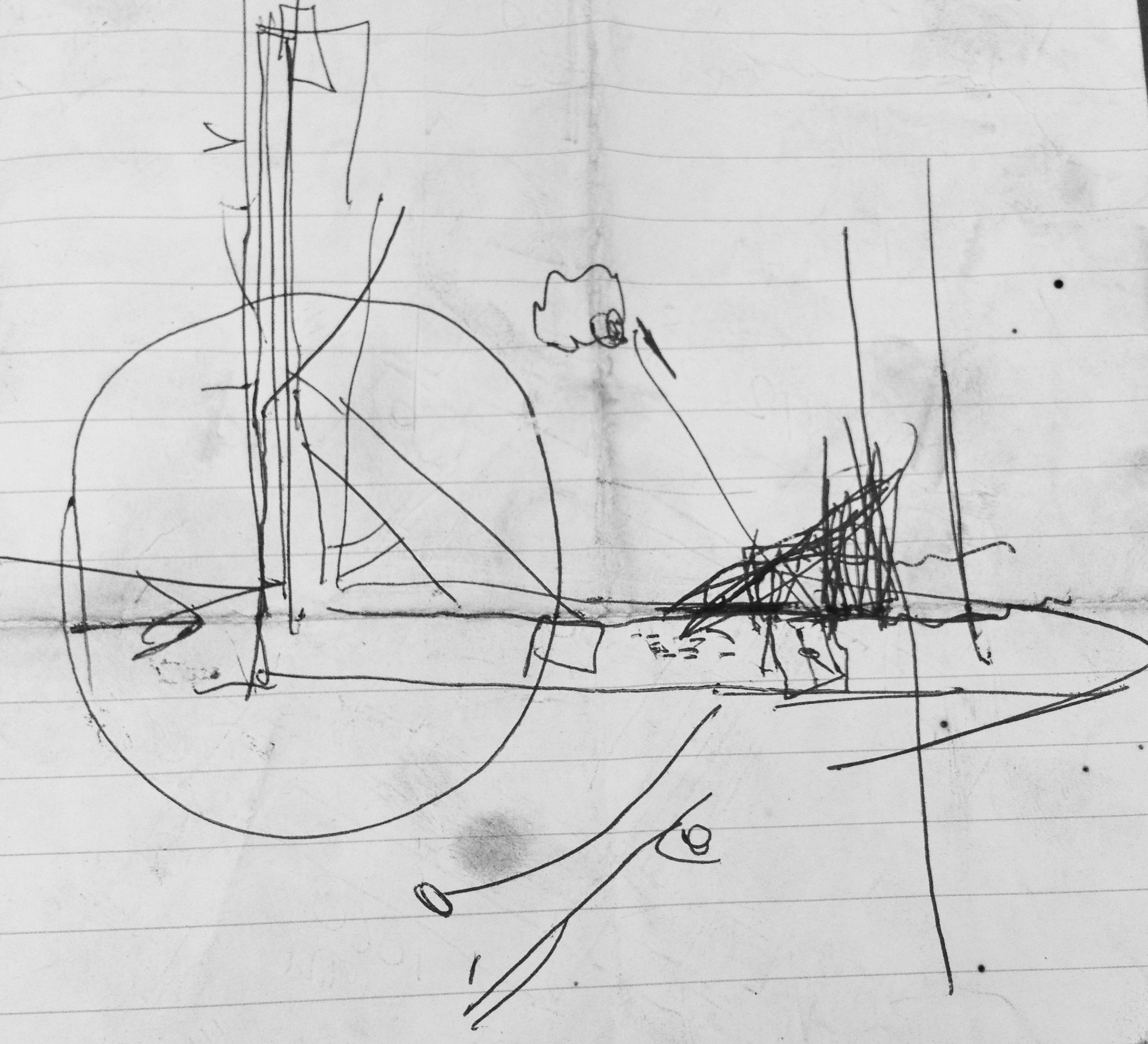
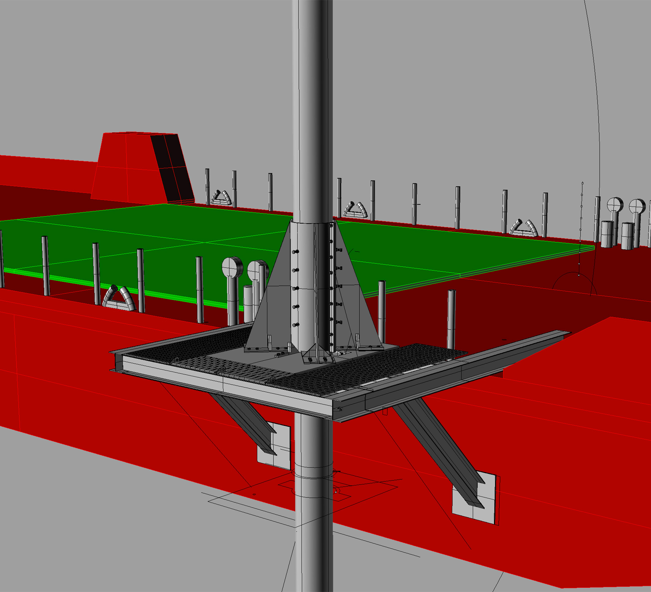
While the chisel was being shipped and after I had measured the work barge, I put together an early draft of the digital design in Rhinoceros 3D.
This process took the better part of a day.
With steel deliveries taking at least 2 days to the island, I had to place my steel order before the final design was complete and estimate my totals and account for any design changes that might take place.
After the steel was ordered, I continued to detail the design and line up such things as holes, bolts, stiffeners etc... (Number of items etc in an application)
Drawings for assembly of the project would need to be clear and easy to read, while still being easy to update. This is not exactly Rhino’s specialty.
Instead I brought the model (via DWG) into Autodesk Revit for design drawings. This worked extremely well and allowed the two programs to interchange data and keep all models linked together.
A few changes had to be made to the model after it was substantially complete and detailed in Revit. The DWG workflow allowed this to happen (feature links could be updated in place with no loss of dimensioning information).
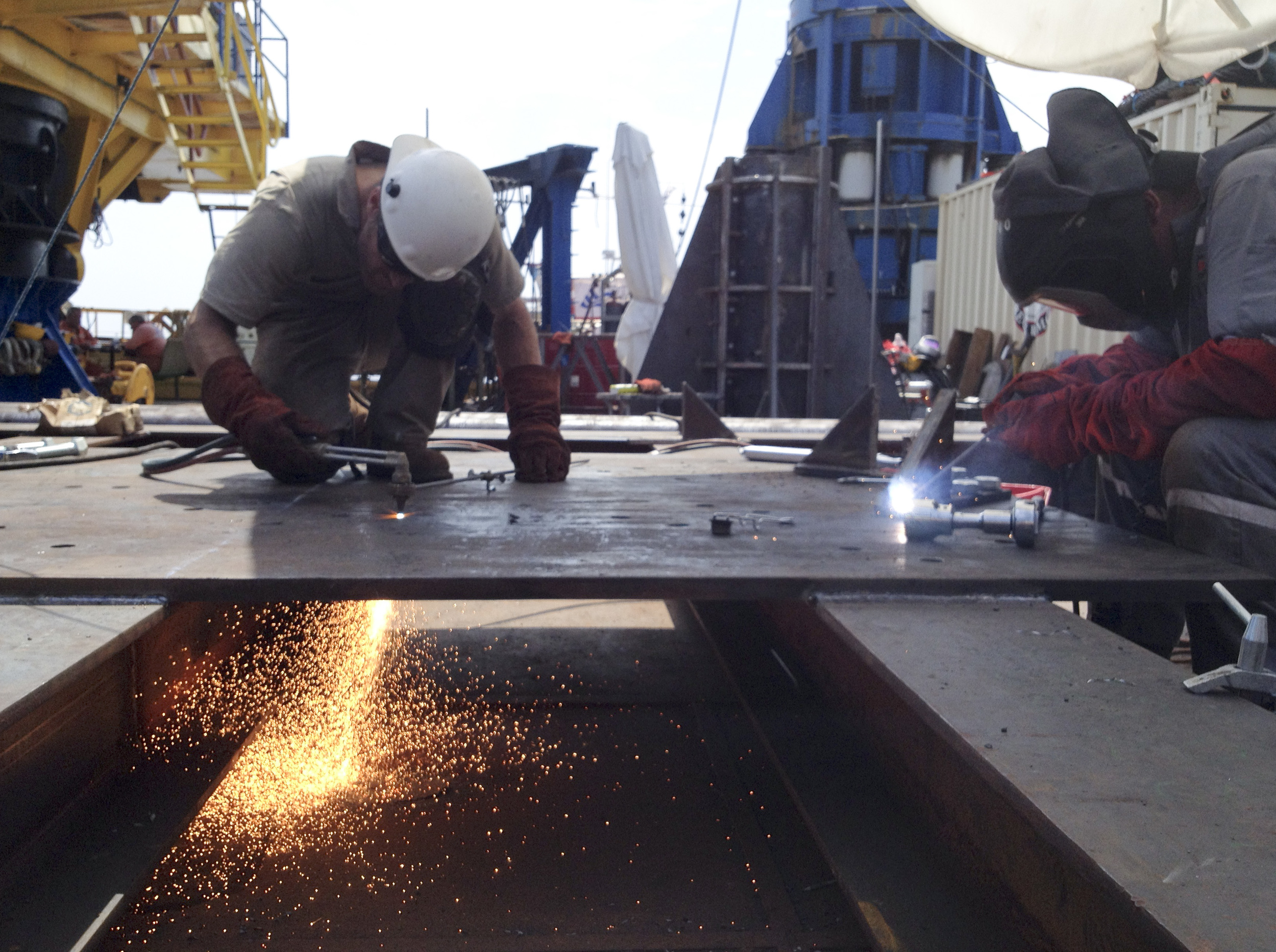
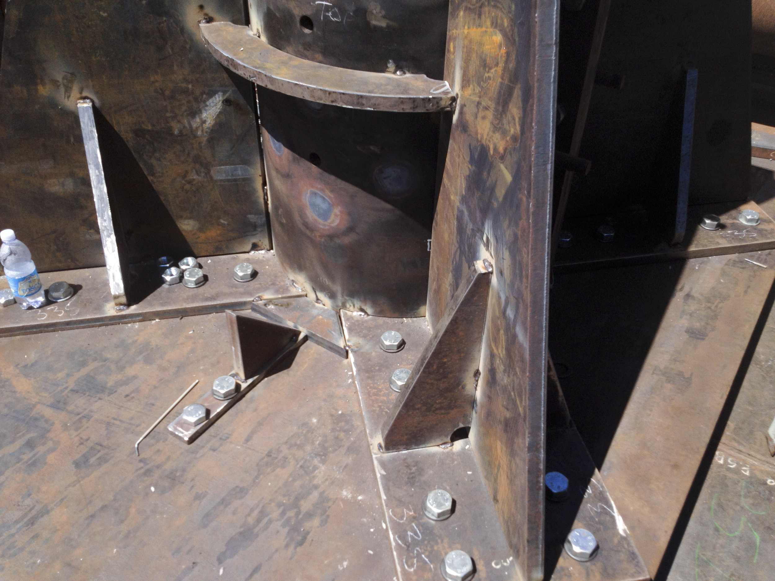
Fabrication commenced based on the drawings produced by the end of day 2.
The ability to create clear, quick and updatable drawings based on an existing 3D model (even when made in another program) allowed this project to be completed with great speed and accuracy.
The project was completed on schedule and worked exactly as required.